Kick the Qu – A DIY Foot Switch for the Allen & Heath Qu-Series
This page used to be a post in a blog called »Zwei« that has been shut down in September 2017. The original post was published in July 2015. Now that the blog is not there any more, this page serves as an archive for this project. This was conceived and written by Niels Ott.
After some years of gigging with an Allen & Heath PA12 console and a side rack, me and my blues and rock band went for a digital console. We chose the Qu-16 over the obvious competitor, the Behringer X32. These were our reasons: a) From previous experience, we have trust in the brand. b) The Qu-16 doesn't have too many features. Since we cannot afford an FOH engineer for almost any gig, we need something that can be operated on the fly once the show is running. c) Still, the Qu-16 is one of the first desks available and affordable that is able to replace our entire side rack consisting of an USB audio interface for recordings, a multi-channel graphic EQ with built-in analyzer, a high-quality FX unit and a gate/compressor unit. And, having unpacked our new gadget, we found: d) The Qu-16 is really small and handy.
Still, there is one issue for bands without an FOH engineer: There is no foot switch option for the Qu-16. Reverb on the vocal mic between songs is a no-go and dropping in a delay in the right part of the song just sounds so great. We managed to solve this problem by creating our own DIY foot switch. And there the story goes…
The Plan
After some thinking, we came up with the following specification of our application:
- Mute status of FX and delay time shall be visible from both the foot switch and on the Qu-16’s surface.
- The foot switch shall allow to mute the reverb on vocals and the delay on vocals separately. Furthermore it shall allow for tapping in the delay time.
- The foot switch shall connect to the console via Ethernet (perhaps even wireless).
To approach this, the Qu-16 is set up in the following way:
- Put the FX sends of engine 1 and 2 of the Qu on mute groups (the sends, not the returns, so that a delay could ring out while something else is already going on).
- Set the user defined keys to operate the two mute groups plus the tap delay. Now you can see what’s going on directly at the Qu's surface. The mute buttons light up, the tap delay button flashes in time.
The foot switch needs three buttons to push and three corresponding LED indicators. A power indicator and a network connection indicator are also a good idea. Unfortunately, the Qu does not support a MIDI command that simply controls the user defined keys, so one has to dig a little deeper.
DIY vs. Others
First of all, a DIY project is never worth the effort if you consider the working time you put into it. Aren't there other options? Yes, there are: One can get a USB-Host-to-MIDI adapter and a MIDI foot switch. The Qu-16 talks MIDI via a class-compliant USB interface. However, there are caveats. The MIDI foot switch must be very flexible in programming, since the protocol of the Qu consists of several events for muting channels (and FX). Even worse, the Qu currently does not accept a ›tap signal‹, it expects delay time to be sent as a time value in its proprietary (but documented) format.
The other option is to program your own foot switch. Send whichever message you want. Include whichever function you need. Drawback: Needs loads of knowledge and time. So let's go.
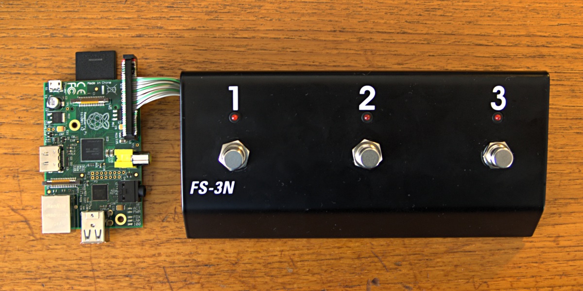
The Raspberry Pi board connected to the other circuitry, later to be mounted inside the housing.
Why a Rasbperry Pi?
The Raspberry Pi is an embedded computer on a credit card size board. It includes 700MHz ARM CPU and 512MB of RAM, an SD card serves as permanent memory. The preferred operating system is Linux. It is purely insane to have 700MHz simply for a foot switch with three buttons and five LEDs. However, there is one major reason to go for the overkill: The author of this article is very familiar with Linux and a reasonably skilled high-level programmer. He is not a hardware guy and he skipped the exam of the lecture on assembler programming when he once tried to study computer science. Things had to be less complicated in order to work out.
The Raspberry Pi has all you need: A standard Ethernet connector, two standard USB host connectors, a general purpose IO connector that can directly drive LEDs and more or less directly can deal with buttons hooked up to it. With Linux as operating system, there are high-level APIs available that allow you to access all that functionality without too much of deep thinking.
Plus, the Raspberry Pi is incredibly inexpensive for what it is.
Choose Your Hothouse
The Raspberry Pi comes without a housing. There are fancy plastic products available for nerds, but none of them comes in the shape and sturdiness required for a foot switch. So this one is a little more tricky. Our solution was to buy a Hughes & Kettner FS-3 guitar amp foot switch. We ripped the guts from it, replaced the latch switches with momentary switches, drilled some extra holes into it, and with a file made those holes fit the connectors of the Raspberry Pi circuit board. Now that was quite some tedious hand work.
Wiring up the Raspberry
The Raspberry Pi has a general purpose input/output interface. It can power LEDs directly when connected via a 270Ω resistor. Furthermore, one can connect switches directly. However, this works only on some of the I/O pins without a pull-up resistor, otherwise the Pi will receive random button presses. (One can also use poll-down resistors. The program code has an ›invert‹ flag for every input.) This is all the wiring, quite simple:
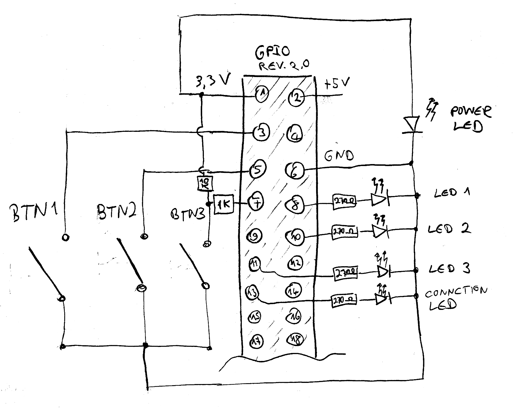
It's not too much of wiring that is required for this project
The power LED naturally comes up as soon as the power supply is connected. LED1 will also light up constantly before the custom made ›firmware‹ is ready. The Python code (see below) will initialize the GPIO interface, switching off all LEDs except for power and bringing up the connection LED as soon as it is able to talk to the Qu-16. In our version, LEDs 1–3 are red (similar to the user key LEDs on the console), the power LED is yellow and the connection LED is green.
Furthermore, a power supply with clean 5V DC is needed. We tried one with 700mA, that did the job. However, for the final version, we made use of an extra circuit board that makes 5V out of anything from 7V to 17V. This allows to use wall warts that are also used for guitar stomp boxes, which gives you some redundancy in case you lose or break the power supply. If you find this useful, search for step-down DC/DC converters on the Web, there are inexpensive ready-made boards available.
Fighting the Python to get it Right
The Raspberry Pi is easy to program in Python on Linux. Well, relatively easy. We went for PiCore, a variant of the TinyCore Linux distribution. It happily lives on some small SD card. Make sure to use the SSH variant of PiCore – this way, you won't get any fancy graphics but remote access via the net, which is very useful once the Raspberry Pi is mounted into the housing, since the HDMI video connector then is out of reach. PiCore does not save anything to the SD card, except you issue a special command. This might seem cumbersome, but it saves the SD card an early death since no write access takes place during regular operation.
Explaining the Python code would now really make this article become a solid book. This is the attempt of a brief summary: Since the author of this blog post comes from a Java background, everything is a bit more designed and comes with a bit more overhead as it would from a pure Python perspective. Forcing those foreign principles onto that snake was quite a bit of a fight.
The design defines handlers, each with a clear responsibility. One handler talks to the hardware (GPIO), one talks to the Qu via Ethernet, one simply generates keep-alive messages, and so on. These handlers run in parallel in separate threads and communicate via a central message controller. Computing tap time is dealt with by a handler, too.
The communication handler talking to the Qu also sends messages about the network status, which is used by the handler driving the connection LED. Furthermore, it goes into a reconnect loop should the connection be gone. Directly after the connection has come up, it requests a status dump from the Qu-16 so that the LED status can be updated according to the status of the console. However, this takes a little while. The code could do with some improvement here, since the handler is slow in reading the large pile of Sysex data via the net.
The software is running solidly but is in a beta state. There is only one developer, which is the author of this blog post. You can simply download a snapshot here. In the probably very rare case that you want to contribute, please do send a message. The code is released under the terms of the GNU GPL v3, but there are third-party files in there. A solution for this issue must yet be found.
Conclusions/Final Remarks
It took quite a while to develop this project and it took even longer to finish a blog post about it. Unfortunately, there is still no easy solution that you can simply download and install. Since the question as come up already: It is very unlikely that we will go into the direction of becoming a manufacturer of such a device. Apart from the legal voodoo, we're too often too busy with our jobs since we can't make a living from music. And when there is free time, we enjoy entering the stage together with our Qu-16. By the way, since the release of firmware version 1.7, the Qu can handle both an iPad App connection and this DIY foot switch simultaneously.
Making something bigger out of this little project would require a development team. Since most people are either good programmers or good sound engineers working with pro equipment, this is unlikely to happen. Nevertheless, by releasing the code as open source, it should be at least possible.
Downloads
- Release 0.1.: Download Source Code (make sure to check README.txt)
Updates and the Future
- August 2016: More recent versions of the QuPad app can trigger the soft keys of the Qu directly. This means that the original program code could perhaps be simplified quiet a lot: the buttons of the foot switch could simply act as soft keys and the Qu console could feed back the LED status as for the soft keys.
- Since March 2016, there is a GitHub repository maintained by Chris Zuercher. Further development will take place there.
- Further reading and exchanging of ideas: Also check out the corresponding thread in A&H's forum.

The finished DIY foot switch live on stage